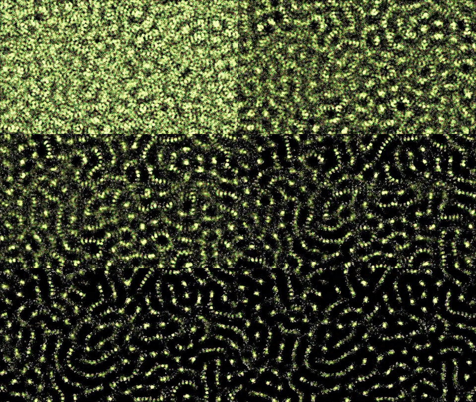
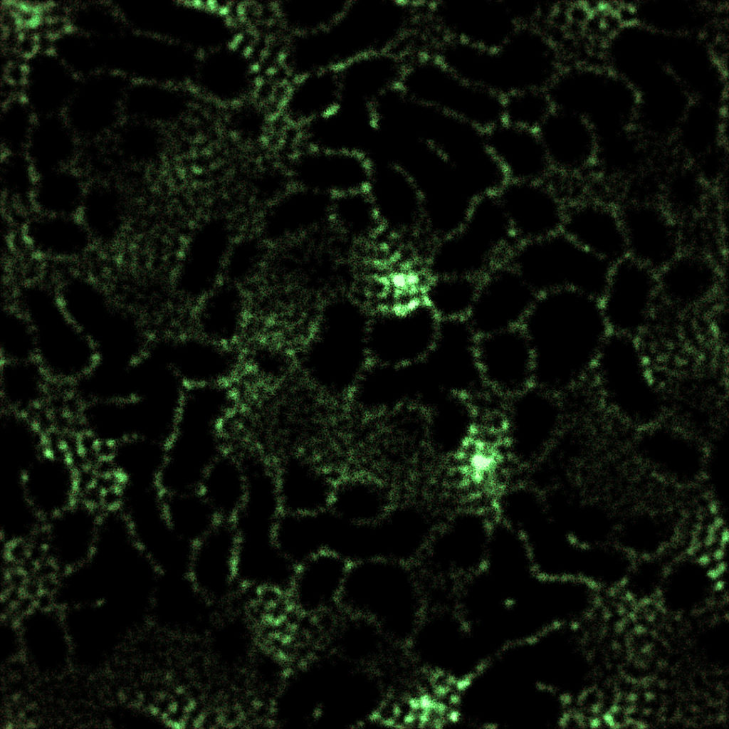
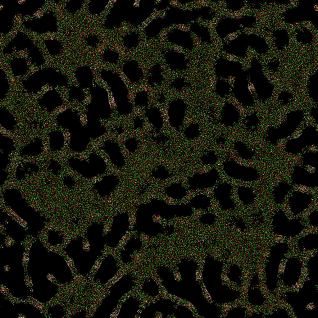
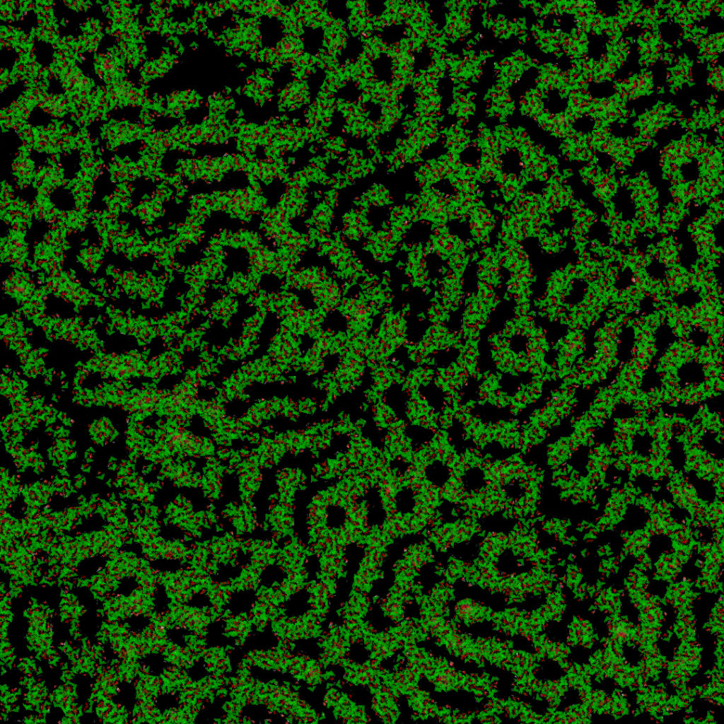
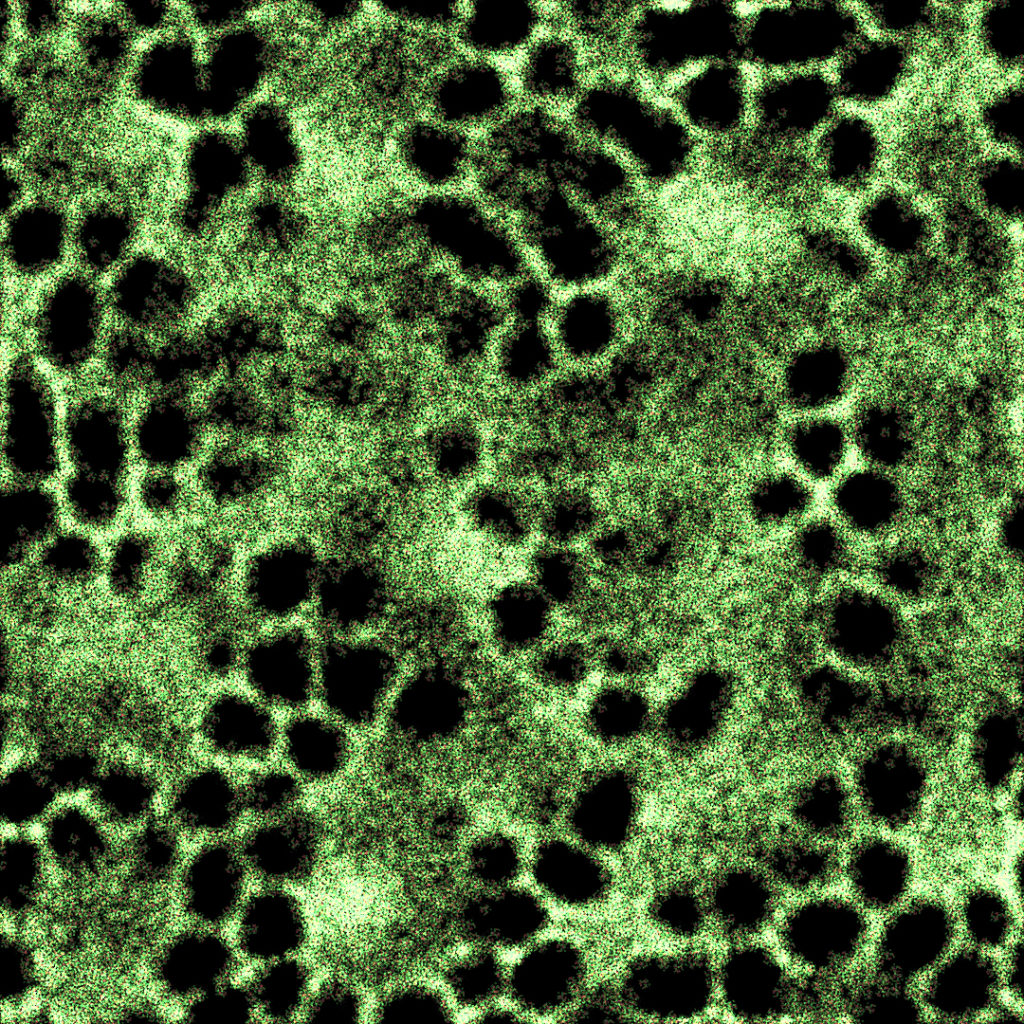
Computational models involving Particle-to-Particle interactions often come at a high computational cost as the number of particles increases. Some techniques propose to handle the interactions between the particles by having them interact with the environment using READ / WRITE operations (Ant Colony Optimisation algorithms [1], Characteristics of pattern formation and evolution in approximations of physarum transport networks [2]). Often times, these models involve agents depositing substrate in the environment, and sampling it using sensors. These systems work well in the case of organic simulations, as it is inspired from different natural phenomena: stigmergy [20, 21], chemotaxis [3]. In this article, I will propose to generalize these type of systems by extending the interactions with a deposited-substrate to a wider range of applications involving particle-to-particle interactions.
1. An introduction through the study of a simple problem
To understand why this technique has a wide variety of applications, we will study one of the most basic systems when it comes to particle-to-particle interactions: an attraction/repulsion system. Each particle is attracted and repelled by each other particle. The strength of the attraction / repulsion very often depends on the distance between the particles. Some systems can implement a physic based model [4], whereas other systems can opt for a more algorithmic solution [5], it depends on the problem the simulation is trying to solve.
In this particular study, we will look at a Localized Attraction-Repulsion [5] system, which I already described on my blog. To sum it up, each particle can be attracted / repelled by each other particle, if it is in the attraction / repulsion range. This algorithm is super simple to implement, and a lot of interesting patterns can emerge by changing the attraction/repulsion range/strength. This is the algorithm in action:
There is an issue with the following algorithm. Because each particle interacts with each other particle, its complexity is at least ![]() . The following curve shows the increase in computational time as the number of particles increases:
. The following curve shows the increase in computational time as the number of particles increases:

If some optimizations can be made to reduce the computational cost (Voronoi Diagrams [6], QuadTrees [7]…), they also come with some downsides. For instance, one could lose the ability to use the GPU and compute shaders [8] to run the simulation because of optimization algorithms which work well on the CPU but do not translate on the GPU. So, we have 2 major issues:
- complexity

- parallelization on the GPU is not trivial (and becomes harder, if not impossible, as optimizations are made to the algorithm)
The complexity issue is for me the most problematic. Often times, I am looking for the emergence of large-scale behaviors in those type of systems. And large scale behaviors can only arise if there is at least a certain amount of particles in the system. Moreover, having such simulations running in real time might be a sine qua none requirement for some projects (for instance, by using javacript the simulation reaches a 60fps limit at 600 particles). By using Compute Shaders, one can greatly improve those simulations. The following example demonstrates the same simulation running on the GPU in real-time with a compute shader, with 12 544 particles:
Despite being a great improvement, 12k particles could still be so little compared to what might be required to see better emerging behaviors.
We are then left with a simple problematic: how can we keep the nature of particle-to-particle interaction systems while getting rid of the computational complexity ? The word nature is quite important there. We would like the emerging behaviors of our systems to be the results of any kind of interactions between the particles. Are there any type of systems in which particles interact together without having to send signals to each other particle of the simulation ? As a matter of fact, there are.
As stated in the introduction, there are particle systems in which particles interact together by using their environment as a communication layer. In those system, particles have the ability to leave some substrate in the environment, and also have the ability to read the deposited-substrate concentration at certain positions (often times by using sensors). If you are not familiar with those systems, I suggest looking at a nice article written by Sage Jenson about a Physarum Polycephalum simulation [9], which is a summary of a paper by Jeff Jones [2].
In those systems, the motion of the particles comes from a decision-making based on the concentration levels of the substrate under the sensors.

If we take the schema above [Figure 2] for instance (sorry for the quality 🙃), and look at the particle in the center and its sensors (in yellow), we can see that there are different concentrations of the substrate (in green) under each sensor. The particle, after getting this information, can for instance decide to take a turn to the right to get closer to some substrate. The following interactive snippet demonstrates this algorithm in action:
Because this system doesn’t require each particle to interact with each other, the complexity is ![]() , which allows us to add more particles more easily, without running into performance caveats:
, which allows us to add more particles more easily, without running into performance caveats:

Compared to the previous graph, we can observe a more linear growth. It should be noted that the growth isn’t completely linear because each particle needs to perform a few operations (such as sampling the environment 3 times), which is why the growth is still exponential, but it takes way more time to be noticed than in the previous system. For this graph, the number of particles I studied was 5x higher than for the previous system. Moreover, each particle of this system is independent. Which makes it a better candidate for parallelization on the GPU (we’ll reach the millions of particles easily there).
That’s great. We have identified another type of systems in which particles still have the ability to interact together, while getting rid of the computation cost involved in checking all the other particles. But how can we generalize this type of substrate-based systems so that they could cover a wider range of use-cases ?
2. Particle interactions using a Communication Layer
At the time of writing, I am only aware of 2 substrate-based particle simulations (other than those that I created):
- Physarum transport network [2]
- Ant Colony Simulation [17]
Both of these systems can be classified as Agent-based models [18, 19]. Agent-based models are systems in which the agents (which can also be thought as particles) are autonomous, and share the same properties. When put together, interactions and actions of these agents make mass-behaviors emerge. In susbtrate-based systems, the particles (ie agents) share a key property: they can leave and read some substrate from the environment.
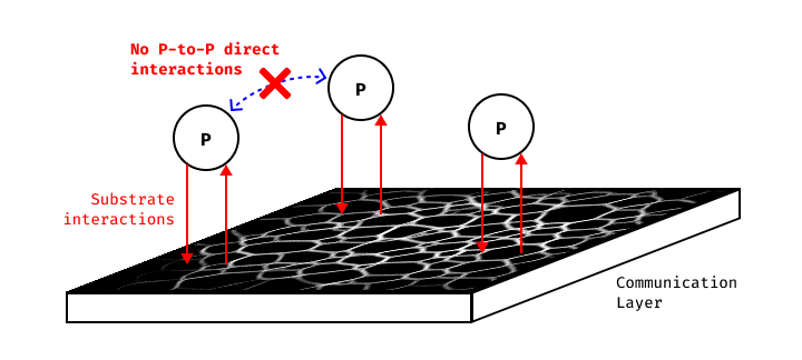
It’s as simple as that: Deposited-Substrate as Communication Layer (DS-CL) systems are agent-based systems in which the agents have the ability to interact with some substrate in the environment in which they evolve. However, from this simplicity comes a lot of diversity, not only in the many possible outcomes, but also in the different decisions we can take when designing such systems.
3. A DS-CL framework
In this section I will propose a framework to describe Deposited-Substrate as Communication Layer systems. This framework is basically a list of all the different parts of such systems. It was made to help in designing, describing and classifying DS-CL systems. For that matter, this framework can also be seen as a description of all the different parts in DS-CL systems.
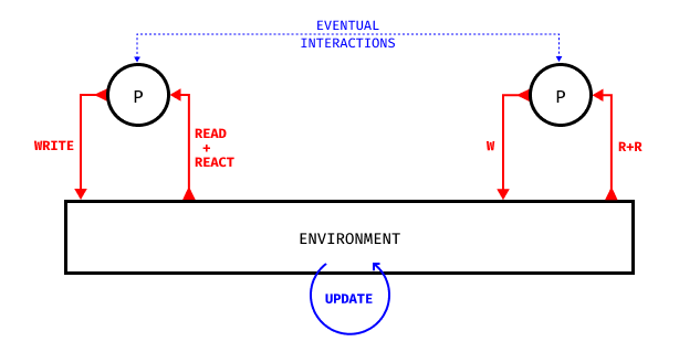
- WRITE: how does the particles apply modifications to the substrate(s) in the environment (both from conceptual and implementation standpoints) ? Do they deposit or can they also remove some substrate ? Where do they add/remove substrate(s) ?
- READ + REACT: how do particles read the substrate(s) in the environment, and how do they react according to it ? I put Read and React operations together because the reaction will always depend on the way the data is read from the environment. They can be described separately though.
- (ENV. UPDATE): how does the environment – and so the substrate(s) – evolve over time ? Is there some diffusion (blur), evaporation (decay), motion (displacement)… ? Is there another system applied on top of it (such as cellular automata CA) ?
- (P-to-P INTERACTIONS): does the system require the addition of true particle-to-particle interactions ? Adding this layer of interactions will come at a computational cost, and will constrain the implementation on the GPU. But it’s important to note the possibility.
Depending on the needs of the simulation, any number of different substrates can be used. DS-CL systems are not limited to only 1 substrate.
For a system to be considered as a DS-CL system, it must implement the WRITE, READ and REACT operations.
4. Deposited-Substrate as a Distance-Map
To extend the potential one can make of the Deposited-Substrate, one can see it as a Distance Map.
Let’s look at the Physarum simulation from another angle. The simulation is an attempt at simulating a transport network. Despite the particles being a core element of the simulation, we are mostly interested in the substrate that is being produced. The particles can be seen as a mean to construct the transport network, not the transport network itself. Let’s take the particles out of the simulation, and only look at the substrate:

One thing can be noted: the whiter the substrate is, the closer we are from the transport network. This statement might seem trivial and perhaps useless, but is in fact the key idea to shift our perspective on this type of systems.
A Distance-Map (also know as Distance-Field or Distance-Transform [10]), is a way to encode the distance to a surface, volume, area in a N-Dimensions grid of cells. Typically, we would store a Distance-Field in an grayscale image.

If we were to take the previous image of the Physarum substrate, we could apply an Euclidean Distance Transform EDT [11, 12] on it to get a proper Distance Field. EDT can take a boolean field as an input (a 2D image in which each pixel is set to true or false) and create a scalar image in which each pixel stores the closest distance to a true value in the input field. This transform could allow any particle in the Physarum simulation, wherever it may be in the 2D world, to know its distance from the closest transport network.
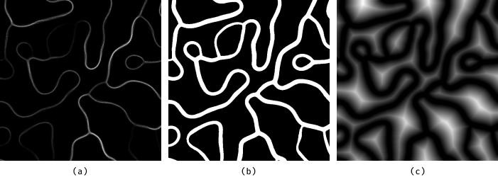
- (a) the original Substrate-Map
- (b) the boolean field (true if substrate > 0, false otherwise)
- (c) Distance-Field after the application of an EDT on the boolean field
Let’s be clear about something important though: applying the EDT will probably never make sense. I just used it as a better visualization tool. The substrate map should be designed in a way that particles can directly interact with it without having to apply any transformations to it.
In the next part, we will see why seeing the Deposited-Substrate as a Distance Map can help in designing some features of particular systems.
5. A direct application of this technique: Attraction / Repulsion
Let’s get back to the first particle-to-particle example we picked at the beginning of the article: Localized Attraction-Repulsion (LAR) [5]. I think the most straightforward way to understand how to apply this technique to any particle system is to go through the design of an actual system.
What are the features of LAR systems ? Particles are attracted and repelled by others if there are in a certain range. In a way, the particles are aware of their distance to the other particles, and react based on that. To make the parallel between the LAR system and the usage of a Substrate as a Distance Map, let’s first compute the Distance Field on the actual LAR system, ie. the distance from any point in the space to the closest particle, so called Voronoi Diagram [13]:
Now let’s invert the Distance Field, so that the whiter it is, the closer we are from some particles:
Let’s think about this for a second. Imagine we were to put a new particle in this simulation, which cannot interact with the other particles, but could only read the data of the Distance Map. By sampling the Distance Map around itself, it could deduce the direction it has to take to get closer to other particles. This is known as estimating the gradient [14]. From a computational standpoint, we could in fact get a pretty good estimate using the following process:
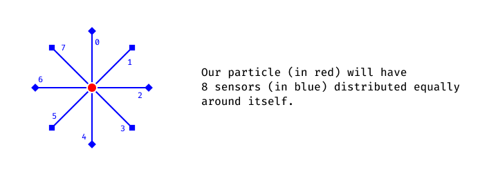
Each sensor has the ability to read the Distance Map and get the value under itself. Let ![]() be the function that returns the value of the Distance Map at
be the function that returns the value of the Distance Map at ![]() coordinates. Let
coordinates. Let ![]() be the number of sensors, in this case
be the number of sensors, in this case ![]() . Let
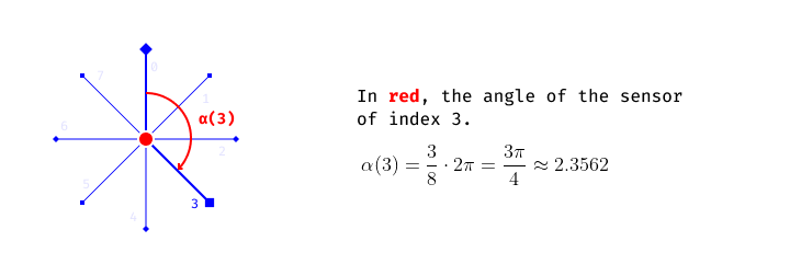
. Let ![]() be the function that returns the angle of a sensor at a given index
be the function that returns the angle of a sensor at a given index ![]() :
:
![]()
The acceleration vector ![]() we can apply to our particle so that it moves where there is more substrate can be computed by averaging the direction of each sensor multiplied by the value of the substrate under itself:
we can apply to our particle so that it moves where there is more substrate can be computed by averaging the direction of each sensor multiplied by the value of the substrate under itself:
![Rendered by QuickLaTeX.com \[\overrightarrow{a} = \sum_{n=0}^{N} \frac{s\Big(cos(\alpha(n))+P_x, sin(\alpha(n))+P_y\Big) \cdot \overrightarrow{\Big(cos(\alpha(n)), sin(\alpha(n))\Big)}}{N}\]](https://ciphrd.com/wp-content/ql-cache/quicklatex.com-c1d9cb46b57c1eb743e0bd76c0a1cad8_l3.png)
where
The following snippet demonstrates this process in an interactive manner. The red vector is the average of the green vectors (scale does not match for better readability). Green vectors are weighted by the value under their corresponding sensors. This is an implementation of what I have just described mathematically:
We have now a way to move a particle based on some Distance Map, in a manner that is better suited for our needs. Let’s try to apply a basic physic model to the particle, and see how it behaves:
That’s great. Our particle is able to move where the local density of the Distance Map is the highest. For our next step, we would like to implement the attraction between many particles. To do so, we first need a way to have the particles create the Distance Map by depositing some substrate in the environment. Basically, we could use the Voronoi Distance introduced properly. But I think a better way to utilize this technique is not by computing the Distance Map, but rather have it be organically created by the particles themselves. The next illustration shows how we can basically create the distance map by drawing a faded circle around the particles:
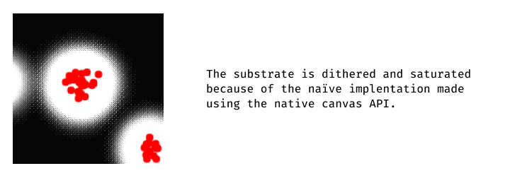
Please ignore the bad rendering quality. This snippets makes usage of the native Canvas API of the browser, and thus I had to use a few tricks to get this working the way I wanted.
We can see that this demonstration is quite similar to the inverted Voronoi Distance we have seen previously. In contrast, in this version when multiple particles are close, the substrate map gets denser, which is better for what we are looking for (grouped particles should attract more than single ones).
On a side note, I think that it should be noted that I have only been using the CPU in the examples I have been showing. But what could be done, is utilize the GPU to create the substrate map instead. This way, by having the substrate/distance map stored in a texture on the GPU, we can easily (and way faster) apply transformations to it, such as blur, displacement… etc. We also have more control on how to write to the substrate map, by using instancing for instance. I will not cover this in this article, as I am only trying to explain the basic idea.
The next step is simple: merge the 2 previous snippets. Let the particles be attracted to the substrate using 8 sensors:
Amazing ! This proves that we are able to replicate the features of the attraction system, without using any communication (except via the substrate) between the particles !
Unfortunately, the poor quality of this bad implementation prevents the system from behaving properly. We will soon have to move to the GPU to take full advantage of it.
Last but not least, we have to introduce the repulsion. The exact same process will be used, but the direction of the acceleration will be inverted for the repulsion step. Also, we have to pick a different sensor offset.
This is not ideal. But at this point, the lack of precision of the substrate is what prevents this example from behaving as expected. Because values of the substrate are stored in a [0; 255] range, too much behavior is lost because of those precision issues. The side-effect dithering is probably not helping as well. It’s time to run this exact same simulation on the GPU !
| Nb Particles | Attr. Sensor Offset | Attr strength | Rep. Sensor Offset | Rep. strength |
| 4096 | 30 | 0.01 | 10 | 0.015 |
This is the same algorithm in action, but with a different implementation. Each particle leaves some substrate just under itself. Then, the substrate is blurred with a 15×15 Gaussian Filter. The substrate is kept over time via a feedback mechanism [15]. The substrate evaporates quickly over time: each frame, it gets multiplicated by 0.6. The substrate is stored in a Float32 buffer, and its values are clamped between [0; 1]. I implemented the system on TouchDesigner, here is the source file:
Here is another shot, with different settings:
| Nb Particles | Attr. Sensor Offset | Attr strength | Rep. Sensor Offset | Rep. strength | Blur Filter | Max Speed |
| 262144 | 10 | 0.007 | 4 | 0.012 | 6×6 | 0.0002 |
In this new illustration, we can clearly observe some features observable in LAR systems:
I hope you were able to understand the general idea behind using the Substrate as a Distance-Map.
The design of such systems requires to think about how particles can interact (WRITE, READ and REACT) with the Deposited-Substrate. With each system will come its own problems, and it’s up to you to find creative solutions to utilize the Deposited-Substrate in the best possible manner (using it as a Distance-Map is only one of them).
6. Some examples of DS-CL systems
Let’s first look at some already existing system, such as Jeff Jones’ Physarum simulation [2], or such as a classical Ant Colony simulation [1]:
| Operation | Implementation |
|---|---|
| WRITE | Particles leave some substrate under themselves, at a certain rate |
| READ | Particles sample the substrate using 3 sensors in front of them (angle and distance can be controlled) |
| REACT | Depending on the concentration under the left, front, and right sensors, the particle will turn left, right, not turn at all or take a random turn. |
| ENV. UPDATE | The substrate is subject to some diffusion and evaporation over time. |
| Operation | Implementation |
|---|---|
| WRITE | Particles leave some substrate under themselves, at a certain rate. If they have food, they leave a FOOD substrate, otherwise they leave a BASE substrate |
| READ | Particles sample the substrate using 3 sensors in front of them (angle and distance can be controlled) |
| REACT | Depending on the concentration under the left, front, and right sensors, the particle will turn left, right, not turn at all or take a random turn. If the particle (ie ant) has some food, it will react to BASE substrate, otherwise it will react to FOOD substrate. |
| ENV. UPDATE | The substrate is subject to some diffusion and evaporation over time. |
As we can see, both systems behave in quite the same way, except for some minor differences. Let’s describe the Localized Attraction/Repulsion example we have just implemented:
| Operation | Implementation |
|---|---|
| WRITE | Particles leave some substrate under themselves, at a certain rate. |
| READ | Particles sample the substrate using 16 (8×2) sensors around themselves. 8 sensors are used for the attraction, 8 for the repulsion. The offsets of attraction/repulsion sensors can be controlled independently. |
| REACT | A gradient estimation is computed for both the attraction and the repulsion. The 2 vector gradients are added to the acceleration of the particle, depending on the attraction/repulsion strengths. Newton’s Law of Motion is applied to update the velocity and position of the particles over time. |
| ENV. UPDATE | The substrate is subject to some heavy diffusion and evaporation over time. |
I was talking before about the possibility to have different substrates in the environment. I have been working on a variant of the physarum simulation, where different species can produce different substrates. Here is a result I was able to get with such a system:
This system is definitely asking to be studied thoroughly, it’s on one of my todos lists 🙄. Here is the implementation details in regards to DS-CL systems:
| Operation | Implementation |
|---|---|
| WRITE | Particles belong to different groups. Each group leaves a different substrate in the environment. Particles leave the substrate just under themselves. |
| READ | Particles can only read the substrate corresponding to their groups. They sample the substrate using 3 sensors in front of them (angle and distance can be controlled) |
| REACT | Depending on the concentration under the left, front, and right sensors, the particle will turn left, right, not turn at all or take a random turn. There are some variations in the turn angles based on the group to which they belong. |
| ENV. UPDATE | At each iteration, each different substrate attacks some other substrate. This is implemented by having a subtraction between the attacked substrate and the attacker, at each cell of the environment. The substrates are subject to some diffusion and evaporation over time. |
Finally, I will present a last system, which has yet to be named (I will probably write an other article about it, which will be linked here when it happens). This is after seeing the following results that I decided to introduce the DS-CL specifications, because I thought a proper framework for this type of systems was required for a good explanation. Also, a lot of my work is made using DS-CL systems, so it will be easier for me to reference this article when I’ll write about some of my systems.
This system has 2 major components. First, the WRITE step is quite unique:
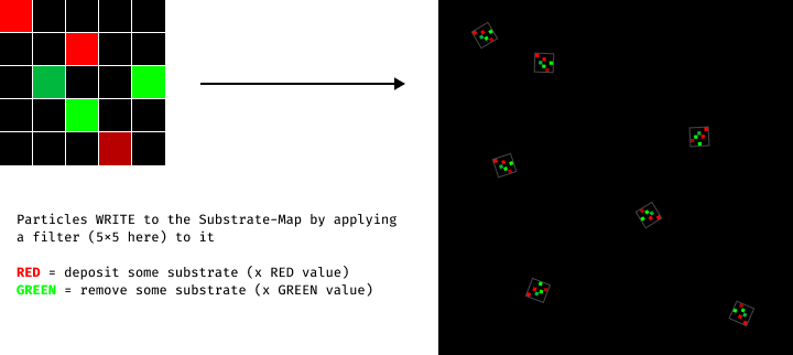
The filter is rotated towards the heading of the particles. I picked Red and Green because I needed 2 different channels to utilize GPU instancing to render the filters on a texture using an additive process.
Then, at each step, particles are sampling the substrate using 8 sensors, in a similar fashion than the algorithm described in part 5. Particles will change their heading so that it aligns with the sensor under which the concentration is the highest. This makes each REACT step independent from the previous one. Particles heading do not have a maximum angle variation at each step.
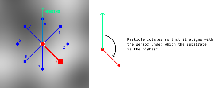
Also, particles have repulsion sensors. If they sample a value with a repulsion sensor that is higher than the highest value sampled with the attraction sensors, then the particle will be heading at the opposite direction of the repulsion sensor in question. This last component allows a rich diversity in the emerging behaviors. Attraction and repulsion sensors have each a different offset value.
Finally, the particles will move in the direction they’re heading, with a fixed step distance.
In the video below, we can see how changing the substrate filter only has a major impact to the whole behavior of the system.
| Operation | Implementation |
|---|---|
| WRITE | Particles deposit and remove substrate by applying a NxN filter composed of RED and GREEN values. (RED = add substrate, GREEN = remove substrate) |
| READ | Particles sample the substrate using 8 attraction sensors and 8 repulsion sensors, distributed evenly around them |
| REACT | If the highest value sampled is under an attraction sensor, the particle will align itself in the direction of the sensor. If the highest value sampled is under a repulsion sensor, the particle will align itself in the opposite direction of the sensor. |
| ENV. UPDATE | Substrate is subject to a high evaporation, and a small diffusion |
epok created a particle system in which particles leave a trace of their velocity in the environment, and such trace influences particles crossing it. You can experiment with his work in real-time on your browser here: https://epok.tech/work/tendrils/.
Again, what’s truly interesting about this system, is the wide variety of patterns it can yield. And I found out that it’s something that is almost true for every DS-CL systems. Because we can tweak so many different parts of the systems, there is an infinite amount of design directions we can take. It can even sometimes be quite difficult to stick up with a particular design, without trying to alter every part of it. But that’s something I consider to be quite beautiful, and I’m happy to have built this framework from which further explorations are going to be much easier.
For instance, I haven’t tried to add true particle-to-particle interactions to any of those systems. Just imagine how much is left for exploration…
Thank you for reading
References
- Ant_Colony_optimization_algorithms, Wikipedia
- Characteristics of pattern formation and evolution in approximations of physarum transport networks, Jeff Jones
- Chemotaxis, Wikipedia
- Newton’s law of universal gravitation, Wikipedia
- Localized Attraction/Repulsion, ciphrd
- Collision Detection Optimization in a Multi-particle System, Marina L. Gavrilova and Jon Rokne
- Efficient (and well explained) implementation of a Quadtree for 2D collision detection, newbedev
- Compute Shaders, Khronos Group
- Physarum, Sage Jenson
- Distance Transform, Wikipedia
- Distance Fields, Philip Rideout
- 2D Euclidean Distance Transform Algorithms: A Comparative Survey, Ricardo Fabbri, Luciano Da F. Costa, Julio C. Torelli and Odemir M. Bruno
- Voronoi Diagram, Wikipedia
- Gradient, Wikipedia
- GPGPU concept 4: Feedback, Dominik Göddeke
- Cellular automaton, Wikipedia
- Ant Colony Simulation, Softology
- Agent-based Models, Wikipedia
- Agent-based Models in biology, Wikipedia
- Stigmergy, Wikipedia
- General Theory of Stigmergy: Modelling Stigma Semantics, Aiden Dipple, Kerry Raymond and Michael Docherty
